Slope based delay
This is a special type of distortion effect, as it reshapes waveform by time displacement instead of altering the amplitude. Many common distortion effects manipulate the amplitude of the signal, typically observed in analog circuitry when overdriving a guitar amplifier. Slope based delay distortion on the other hand, will not change the amplitude of the signal, but modulate the phase to generate harmonic distortion. In this respect slope based delay distortion is related to the synthesis technique frequency modulation, if it is implemented as phase modulation and using the carrier signal both as carrier and modulator. The main reason for presenting it here as a distortion effect is that it sounds like a distortion effect, and was also first presented as part of a distortion effect by Hans Mikelson
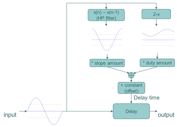
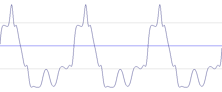
The range for the parameter values are quite small related to the more common drive or gain parameters found in overdrive distortion effects, where 1 equals unity gain. In slope based delay distortion the parameters control delay time for phase offsets so naturally the values will be quite small. There are two adjustable parameters:
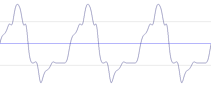
- Slope: sets the amount of influence the waveform slope will have on the delay time. A sharply rising waveform will give a longer delay time and a sharply falling part of the waveform will give a shorter delay time. Higher values for slope will give more distortion at high frequencies.
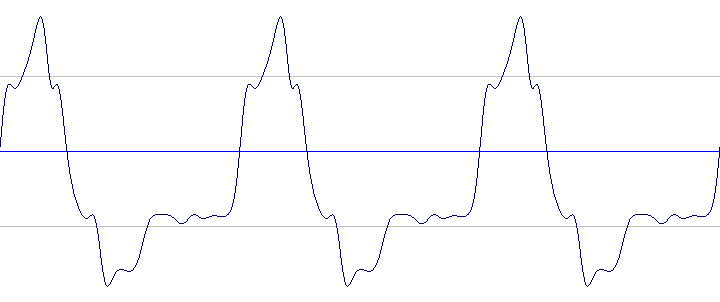
- Duty: sets the amount of influence the waveform amplitude will have on the delay time. Higher values for duty will give more distortion at higher input amplitudes.
When considering the parameter values, remember that longer delay time means more phase modulation and subsequently a more distorted sound. The slope based delay effect can easily introduce aliasing, especially with high values for slope (above 0.02 or so, depending on the frequency content of the input sound and the sample rate), so running a lowpass filter on the input signal to this effect may be a good idea.
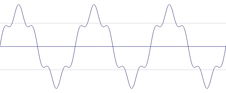
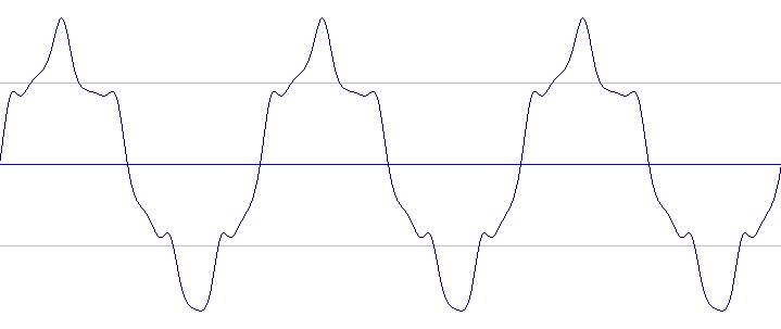
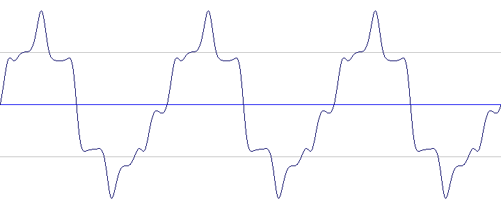
Audio signal graphs
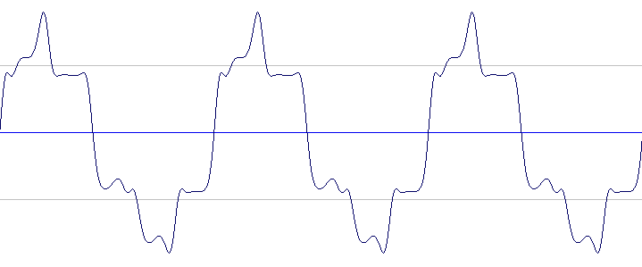
We'll use a sine wave with an added 5th harmonic component as the input waveform to better show how the effect reacts to different frequency components. Note how the waveform acquires new crests and troughs, as the varying delay leads to reading the same sections of the input waveform several times.
Sound examples
Enveloped 440 Hz Sine wave, to be used as input
Sine input, slope = 0.0045, duty = 0
Sine input, slope = 0, duty = 0.0005
Sine input, slope = 0.002, duty = 0.001
Enveloped 440 Hz Sine wave with added 5th harmonic, used as source
Sine with 5th harmonic as input, slope = 0.0045, duty = 0
Sine with 5th harmonic as input, slope = 0, duty = 0.0005
Sine with 5th harmonic as input, slope = 0.002, duty = 0.001
Clean sample, to be used as example input
Sample as input, slope = 0.0034, duty = 0
Sample as input, slope = 0.0, duty = 0.0004
Sample as input, slope = 0.0001, duty = 0.0001
Sample as input, slope = 0.0003, duty = 0.0003
Sample as input, slope = 0.0015, duty = 0.001
Csound code
The following Csound code generates a sine wave and processes it with slope delay distortion.
;***************************************************
; slope based delay distortion
;***************************************************
	instr	1

	iamp		= ampdbfs(p4)	; Amp in -dB
	islope		= p5		; amount of slope influence on delay time
	iduty		= p6		; amount of duty influence on delay time

; audio generator
	a1		oscili	1, 400, giSine

; distortion

	an1		delay1	a1	; delay audio by 1 sample
	aslope		= a1 - an1	; find difference between samples (= slope of the waveform)

	; delay time offset to avoid delay time less than zero
	ioffset		= (0.5*iduty) + islope + 0.001

	; delay line processing
	atemp    	delayr  1
	a2     		deltap3 ((1-a1)*iduty) + (aslope * islope) + ioffset
			delayw  	a1

; audio out
	out		a2*iamp
	endin
;***************************************************