Allpass filter
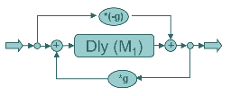
The allpass filter is a filter that ideally passes all frequencies with equal gain. This may sound confusing to some readers, why use the term filter for a process that does not remove any part of the signal? Generally in signal processing we use the term filter for any operation done on a signal. Now, an allpass filter consists of a delay line structure with feedback so it will prolong the sound. It will also pass all frequencies with equal gain, so it seems like a good candidate for design of a reverb algorithm.

As a comparison to the comb filter, let’s listen to single allpass filters too. We will use the same delay times and filter coefficients as for the comb filter examples.
Input sound 1: Short burst of white noise
Input sound 2: A short guitar phrase
Noise burst with allpass filter, M=500, g=0.8
Guitar with allpass filter, M=500, g=0.8
Noise burst with allpass filter, M=900, g=0.8
Guitar with allpass filter, M=900, g=0.8
The following code shows a Csound implementation of a single allpass filter
;***************************************************
; allpass filter
;***************************************************
	instr 2

; initialization
	a1		in				; read audio
	iM1		= p4				; delay time in number of samples
	iM1		= iM1*(1/sr)			; convert delay time from samples to seconds
	ig1		= 0.8				; feedback gain of filter (coefficient)
	adel1  		init   0			; initialize the feedback signal

; allpass filter
	aout   		= adel1+(-ig1*a1)       	; Feed Forward
	adel1  		delay  a1+(ig1*aout), iM1   	; Delay and Feedback

; audio out
			out aout
	endin
;***************************************************
In and of itself, a single allpass filter will not do much in terms of reverberation, so we have to combine several of them. An important issue when combining several of these filters is to choose delay times of nonharmonic proportions, so that the delay taps does not line up with each other. Delay times of integer ratios will make constructive or destructive interference, much like in a comb filter. An early (1962) reverb design by Manfred Schoeder uses several allpass filters in series.

Here’s an example of 3 allpass filters in series, using nonharmonic delay time ratios and a common allpass coefficient of 0.7.
Noise burst with 3 allpass filters in series
Guitar with 3 allpass filters in series
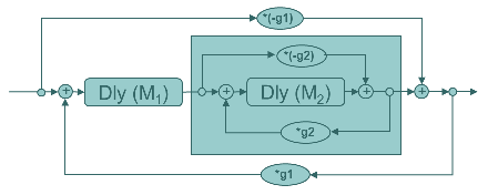
One of Schroeder’s designs use a nested allpass filter, which means that an allpass filter is “wrapped around” another allpass filter. Since each of them ideally does pass all frequencies, the nested allpass will also have this characteristic. We need to take care about the delay time relationships though, to avoid coinciding delay taps.

Combining the serial and nested forms can be quite effective in creating a delay tap pattern that will become more dense over time, as would also be natural in a real room. Here is an example of three allpass filters in series nested in one outer allpass. This form is called a triple nested allpass. In the sound examples below we use M=501,707 and 911 for the serial allpasses, and M=1581 for the outer allpass, a common gain of 0.6 is used for all filters. The parameters could be tuned further.

Noise burst with triple nested allpass
Guitar with triple nested allpass
The following code shows a Csound implementation of a triple nested allpass filter
;***************************************************
; triple nested allpass filter
	instr 2

; initialization
	a1		in				; read audio
	iM1		= 501*(1/sr)			; convert delay time from samples to seconds
	iM2		= 707*(1/sr)			; -"-
	iM3		= 911*(1/sr)			; -"-
	iM4		= 1581*(1/sr)			; -"-
	adel1  		init   0			; init signal, because it is read before it is written
	adel2  		init   0			; -"-
	adel3  		init   0			; -"-
	aout4  		init   0			; -"-
	ig		= 0.6				; filter gain

; triple nested allpass filter
	adel4  		delay  a1+(ig*aout4), iM4  	; Outer Delay and Feedback

	aout1  		= adel1+(-ig*adel4)	       	; Feed Forward
	adel1  		delay  adel4+(ig*aout1), iM1   	; Delay and Feedback

	aout2  		= adel2+(-ig*aout1)	       	; Feed Forward
	adel2  		delay  aout1+(ig*aout2), iM2  	; Delay and Feedback

	aout3  		= adel3+(-ig*aout2)	       	; Feed Forward
	adel3  		delay  aout2+(ig*aout3), iM3  	; Delay and Feedback

	aout4  		= aout3+(-ig*a1)	       	; Outer Feed Forward


; audio out
			out	aout4
	endin
;***************************************************